
 Tweet
Tweet
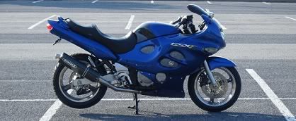
I have given into my desires for installing HID/projectors in the Kat. I've read a bunch of posts and did a lot of internet searching... Here is what I have come up with:
Projectors:
Ballast Kit:
Bi-Xenon Wiring Harness:
Time Delay Relay:
Explanation of Components
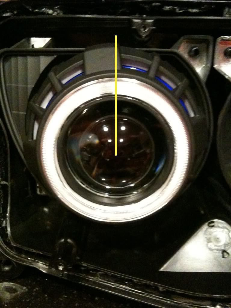
Projectors: Projectors are not needed for HID conversion, but should be used to gain the most performance from the HID bulbs and prevent blinding other drivers. These will also help you gain less attention from cops as it may be illegal to convert your headlights to HID in some states.
Ballast Kit: When buying projectors, you will not receive the ballasts for firing the bulbs. Want HIDs? Need a ballast kit.
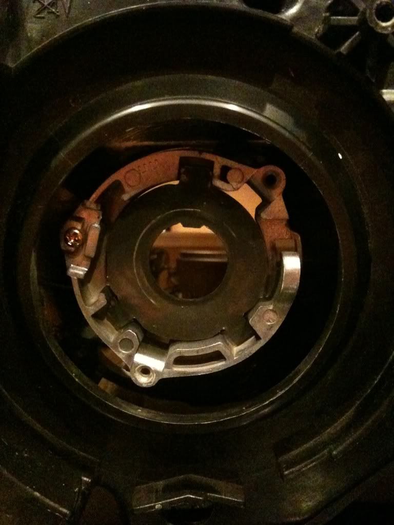
Bi-Xenon Wiring Kit: Probably not required as there are likely some do-it-yourself ways around this harness, but this harness will plug into your stock bulb socket and provide outputs to the solenoids on your projectors to maintain the hi/lo switch operation.
Time Delay Relay: Again probably not absolutely needed, but this relay will delay the power going to the ballasts. This is a precaution to help the life of the ballasts and bulbs during low & intermittent power levels during startup.
Wiring Diagram
Here are two wiring diagrams I have come up with. One or both or neither may be right. I need some knowledgable people to help me with this.
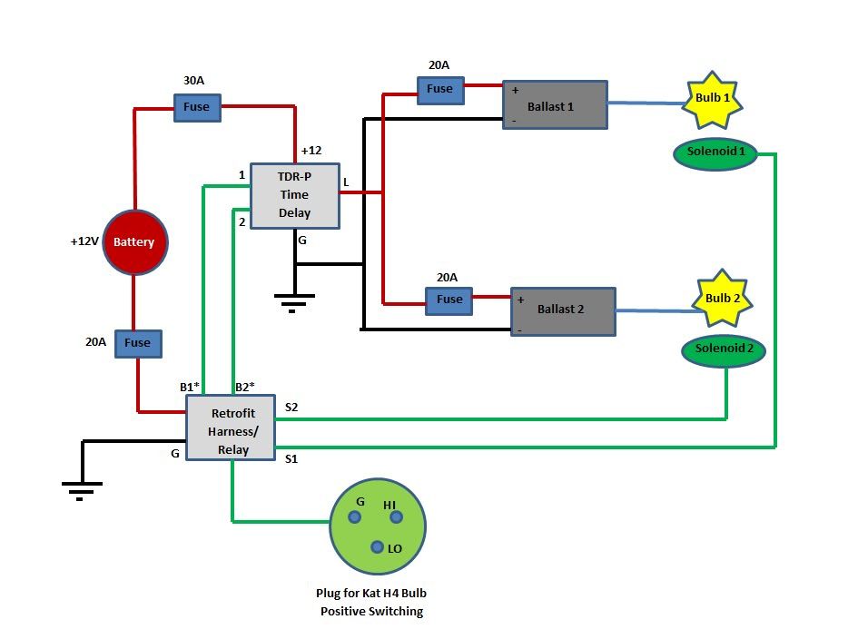

The outputs of the retrofit harness (B1 & B2) are intended go to the +12V of the ballasts. But since we want the power to time delayed through the second relay, the first diagram shows this power going to the "1" & "2" connections of the timed relay. This means that both "1" & "2" will be getting power all the time, when it is supposed to getting power on "1" or "2"... So this may be incorrect. I am guessing the "1" & "2" are for the low voltage source to trigger the relay on. EDIT: For this configuration maybe only connecting one of the connections from the retrofit relay to the timer relay is what is needed since it will always be on.
The second diagram uses the second headlight plug to fulfill the "1" & "2" inputs of the timed relay. Leaving the ballast outputs of the retrofit harness going nowhere.
EDIT: When ordering the time delay relay there are a couple different options. TDR-P will wait the set time when triggers are switched. That means that between switching from hi beam to lo beam you will be in darkness...not good. The company in the link above also sales a TDR-PS version which only waits the delay time the first time it is powered on. This will eliminate the problem mentioned above, but it says it must be wired through a switched ignition source. That means you will be drawing power through your stock harness somewhere...not good. I believe the solution will be to take the B1 output of the retrofit harness to #1 of the TDR-P relay. This output will always be switched on because the bike is always in hi beam or low beam, and only trigger the TDR-P when the key is in the 'on' position.
Once I get some feedback on this I will update the wiring diagram to reflect the proper connections.
Projectors:
Ballast Kit:
Bi-Xenon Wiring Harness:
Time Delay Relay:

Explanation of Components
Projectors: Projectors are not needed for HID conversion, but should be used to gain the most performance from the HID bulbs and prevent blinding other drivers. These will also help you gain less attention from cops as it may be illegal to convert your headlights to HID in some states.
Ballast Kit: When buying projectors, you will not receive the ballasts for firing the bulbs. Want HIDs? Need a ballast kit.
Bi-Xenon Wiring Kit: Probably not required as there are likely some do-it-yourself ways around this harness, but this harness will plug into your stock bulb socket and provide outputs to the solenoids on your projectors to maintain the hi/lo switch operation.
Time Delay Relay: Again probably not absolutely needed, but this relay will delay the power going to the ballasts. This is a precaution to help the life of the ballasts and bulbs during low & intermittent power levels during startup.
Wiring Diagram
Here are two wiring diagrams I have come up with. One or both or neither may be right. I need some knowledgable people to help me with this.
The outputs of the retrofit harness (B1 & B2) are intended go to the +12V of the ballasts. But since we want the power to time delayed through the second relay, the first diagram shows this power going to the "1" & "2" connections of the timed relay. This means that both "1" & "2" will be getting power all the time, when it is supposed to getting power on "1" or "2"... So this may be incorrect. I am guessing the "1" & "2" are for the low voltage source to trigger the relay on. EDIT: For this configuration maybe only connecting one of the connections from the retrofit relay to the timer relay is what is needed since it will always be on.
The second diagram uses the second headlight plug to fulfill the "1" & "2" inputs of the timed relay. Leaving the ballast outputs of the retrofit harness going nowhere.
EDIT: When ordering the time delay relay there are a couple different options. TDR-P will wait the set time when triggers are switched. That means that between switching from hi beam to lo beam you will be in darkness...not good. The company in the link above also sales a TDR-PS version which only waits the delay time the first time it is powered on. This will eliminate the problem mentioned above, but it says it must be wired through a switched ignition source. That means you will be drawing power through your stock harness somewhere...not good. I believe the solution will be to take the B1 output of the retrofit harness to #1 of the TDR-P relay. This output will always be switched on because the bike is always in hi beam or low beam, and only trigger the TDR-P when the key is in the 'on' position.
Once I get some feedback on this I will update the wiring diagram to reflect the proper connections.


 Sounds reasonable. And good to know about the time delay.


Comment