Ad Widget

Collapse

Announcement

Collapse
No announcement yet.
X

Y2KTJ's $50 1990 gsx600f build

Collapse
  • Filter
  • Time
  • Show
Clear All
new posts

  • #76
    I've had a RK chain for about 20,000 miles now ! But, I oil it daily just before I ride and I clean it about every month or two.
    I was told JT sprockets are the best, so thats what I've been using on the front. They're cheap (in cost) and on ebay.
    I had an expensive Supersprox on the rear for about 15,000 mile before it bit the dust. Just got a factory replacement on it now. I guess its Suzuki.
    My Katana-1100 17" wheel swap
    http://katriders.com/vb/showthread.php?t=136894

    Comment


    • #77
      I ment to look at and snap some pics of my sprockets to see if they really need changing. On a budget and want to just slap a chain on it. How necessary is it to replace them with the chain? Guess my question is if they are in decent shape is it necessary to replace them right away? I doubt I'll ride it much in the next year. I need to get my license and with my learners I'll have to ride with others with a bike licenses. Have a few buddies who are willing to take me out but won't be every weekend or anything so it won't see to many kms in the next year. As I type I'm thinking that the po had a loose wheel so I should just replace them. Thoughts?? Will a few hundred kms be that hard on the chain?

      Spent some time trying to figure out the wiring issue tonight. The orange and blue wire I thought was missing from the right switch pod was actually just a loop back to the plug.

      I need some advice on how to diagnose it. I don't want to take the ignition out if I don't have to because it has those stupid non-bolts on it. Need to "knock" them out. I've got a volt meter and basic electrical knowledge.

      The plug to the ignition has 4 wires. 2 have power. When plugged in with the key off still only have power at those 2 on the battery side. Key on all 4 so I think the switch is good. So where else could the gauge lights be getting the power. I look at the wiring diagram and it makes sense but I'm missing something.

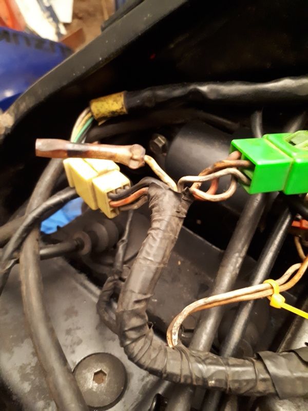
      And this yellow and white wire by the ignition plug looks used and has power but no idea where


      And same with this one by the battery.
      Last edited by y2ktj; 12-28-2018, 03:02 AM. Reason: Automerged Doublepost

      Comment


      • #78
        Stumpt me ! I don't know any thing about the wiring.
        As for the sprockets, thats a judgement call you need to make on your own.
        If I tell you to just go riding and you crash, then its my fault. I'd say go with your gut and use your brain. Was that a oxymoron ?
        EDIT: To answer myself. No, that was a Paradox
        Last edited by katanarider; 12-28-2018, 03:50 AM.
        My Katana-1100 17" wheel swap
        http://katriders.com/vb/showthread.php?t=136894

        Comment


        • #79
          Measure with the plug not connected to the ignition there should only be one 'HOT' wire the red. The red connects directly to the battery there is a junction between the battery and the switch where the red splits off to the alternator, when switched on the power is then supplied back to the fuse box and alternator via the orange wire.
          The orange wire to the alternator causes the alternator to work when rotating.

          In "park" (far left) the red wire supplies power to the parking light circuit (brown) When on "run" (far right) the fuse box will supply power to the lights.

          With the switch "off" no power should be supplied anywhere if you have two "Hot" wires going into the switch, check at the plug, and there is some alteration to the wiring

          Disconnect the battery, disconnect red from starter relay (there's also a direct connection to starter motor), pull ignition fuse (all all of them) and unplug ignition switch.

          There should not be any continuity (circuit) from the red to the remainder of the wiring.

          Yellow white are head light circuits and with switch "off" there should not be any power there.

          Solid colors are primary circuits Red is direct power orange is secondary after the switch and then all other power supplied are orange/something (either white, black, green, red etc etc

          Somewhere along the line the red is connected directly to another circuit some likely the lighting circuit. Start from the battery and see where the red goes would be my first check. Remember red should only go to the alternator, relay and the ignition switch
          Last edited by Lachie; 12-29-2018, 01:45 AM.
          “Anything that happens, happens. Anything that, in happening, causes something else to happen, causes something else to happen.
          Anything that, in happening, causes itself to happen again, happens again. It doesn’t necessarily do it in chronological order, though.”
          ― Douglas Adams

          Comment


          • #80
            Awesome thanks for the post. Definitely positive at 2 points on the ignition plug. Wire loom looks stock as the factory coating is still there. I did have to replace the fuse block as the PO lost it during a divorce. Maybe I got the wrong part. Bolts in and the plug fits. Pre and post blocks the same? Maybe I got a post block. The jeeps tcase shit the bed right before our skiing trip so going to have to work on it before the bike. But when I take a break I'll look at the bike.

            I'm not a complete newb with electronics and wiring when it comes to the basics like wiring stuff in and soldering. But don't have much experience diagnosing issues. Going to do a search on checking continuity now as it's something I haven't done. I'm guessing my volt meter will do this? I see people talking about checking ohms. Is this the same thing? Any advice or terms to search for are appreciated.

            edit: Google searched and got the continuity figured out. I'll check it next time I'm out there and make note of what color wires I'm getting power at the plug and go from there
            Last edited by y2ktj; 12-29-2018, 04:34 AM.

            Comment


            • #81
              So the site was down and I couldn't check what you suggested so did my best while taking a frustration break from the jeep.

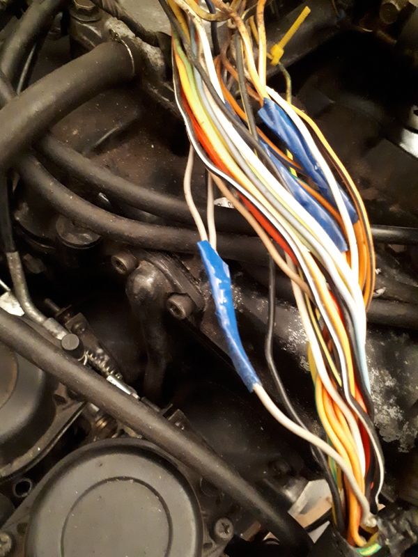
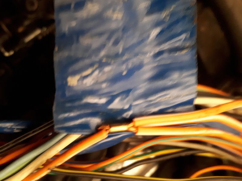
              With the key off, plug has power to the red and gray wire. Peeled off the tap from the top portion of the harness and saw this!

              First thought was a wiring hack job. Under the blue tape looks like a factory splice. Correct me if I'm wrong.

              Followed the grey to the fuse block. Pulled the first fuse and no power at the grey wire.
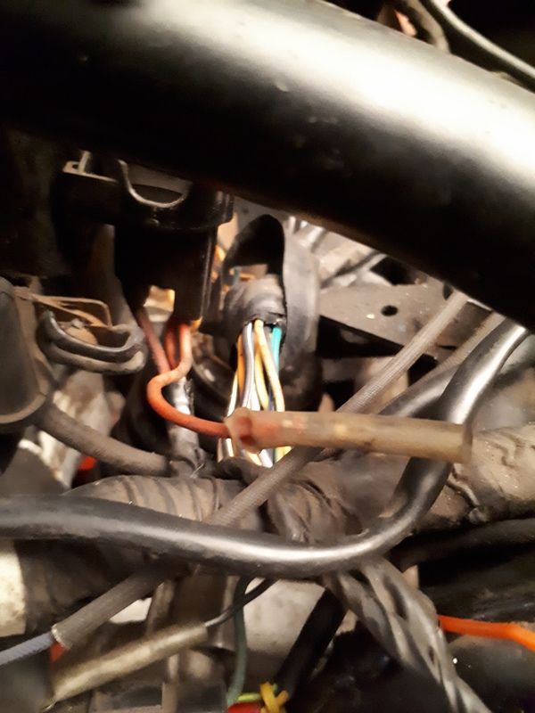
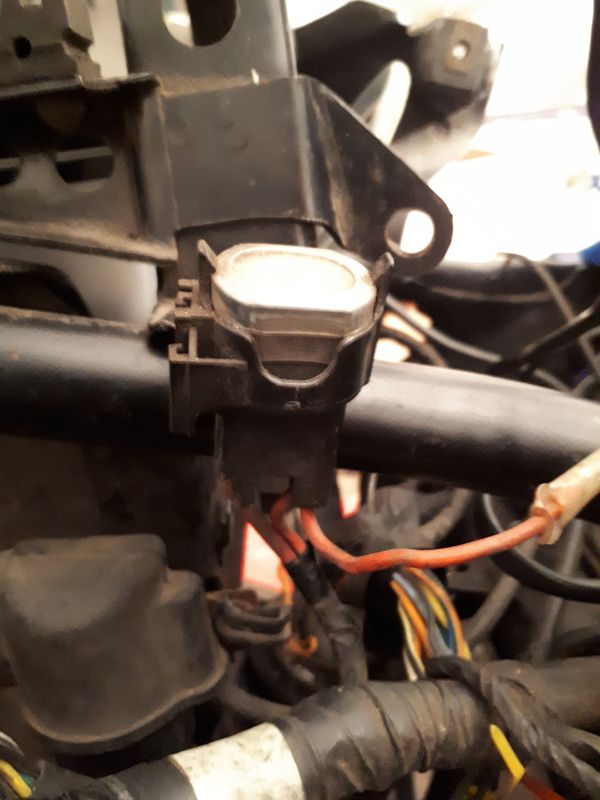
              So went to the battery end and followed the red wire. It goes from battery to a junction and then to this thing. red then goes to the block.


              I'm guessing this is the switch that should be turned on by the ignition that you mentioned Lachie? As you can see in the photo there is a red wire that I can't find a mate to. Am I on the right track?

              Edit: I've checked all my plug connections. And besides the red wire pictured above there is a black and white wire with dual plugs just below the battery box with no mate and this yellow ( maybe yellow and white) wire by the ignition plug.
              Last edited by y2ktj; 12-31-2018, 10:57 PM.

              Comment


              • #82
                Yes that is a factory splice.
                That is the main circuit breaker. See the red dot on top? If it trips push the dot to reset

                The manual is available in mechanics 101. Wiring diagram is in it.
                There is an odd hot wire in the dash area, I’ll guess it’s being used for the dash. I’ll pull the diagram and have a peak see.
                Last edited by 92xjunker; 01-01-2019, 12:28 AM.
                "I'm sorry, I didn't mean to upset you when I called you stupid. I thought you already knew..."
                spammer police
                USAF veteran
                If your a veteran, join the KR veterans group

                Comment


                • #83
                  Ok thanks 92. I downloaded the manual from your post along time ago and thanks for that. When looking at the diagram it all makes sense as far as the principal of it all. But then looking at all the wires on the bike it's not so simple. I talked to the PO and he never had any issues with the gauge lights or battery dieing. He said he never messed with the wiring with the exception of the rear blinkers. He spliced in the replacements and that's it.

                  I followed the hot grey wire back to the fuse block. Could the replacement fuse block be the wrong one? The harness plug fits and the mounts too.

                  Comment


                  • #84
                    Ok, here it goes
                    Starting from the battery +: circuit breaker, T’s off to the fuse box and the ignition switch, from the switch: gray feeds the right hand control and the instrument lights. Orange feeds back to the alternator regulator, fuse block for the main electrical functions ( hense the alternator regulator faults-heavy load on that circuit) Brown feeds the front and rear parking lights and the plate light. Black/white is the - Keep in mind there is an accessory supply wire in the pod area, the diagram does not show plugs that are not used. The yellow wire by the battery is for carb heaters-used only on euro models.

                    I don’t see a gray wire on the fuse box. Not on mine either. There is a negative feed to the fuse box, but it’s black and white.

                    Questions, answers and posts pertaining to electrical mods and problems
                    Last edited by 92xjunker; 01-01-2019, 12:36 AM. Reason: Automerged Doublepost
                    "I'm sorry, I didn't mean to upset you when I called you stupid. I thought you already knew..."
                    spammer police
                    USAF veteran
                    If your a veteran, join the KR veterans group

                    Comment


                    • #85
                      last post before the wife gets mad. lol The grey wire from the ignition plug is pictured above and splits. One goes to the gauge lights and the other end goes to the fuse block that is getting power from the red wire. Should I have power at the fuse block with key off?

                      Comment


                      • #86
                        Only on the 15amp fuse. It feeds the ignition switch. All others are fed by the ignition switch once on. I think you lost the gray wire in the loom, it should lead back to the tail lighting, black and white goes to the fuse box.
                        Last edited by 92xjunker; 01-01-2019, 12:57 AM.
                        "I'm sorry, I didn't mean to upset you when I called you stupid. I thought you already knew..."
                        spammer police
                        USAF veteran
                        If your a veteran, join the KR veterans group

                        Comment


                        • #87
                          ok I'll check it again. Was on and off during jeep breaks yesterday and I've had a couple drinks tonight. lol I didn't strip all the wire coating, just the top portion starting a few inches below the split above the motor and a few inches around some other junctions. Next time I'm out there I'll strip all the coating.

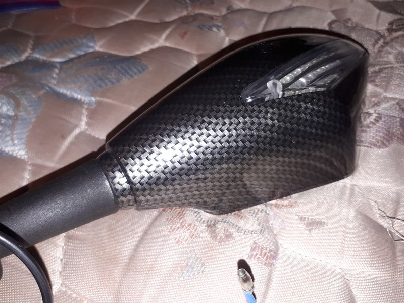
                          Received my new mirrors with integrated blinkers today but true to Ebay form they are carbon fiber and not the black I ordered and the coating is slightly damaged as well. The mirrors themselves seem solid enough for the $30 I paid. I'll juat slap some black paint on them if Ebay refunds my money.
                          Everyone loves pics so here's one I sent to the seller to show the finish.

                          Comment


                          • #88
                            Just to confirm, the ignition switch has several settings. Park is all the way turned counter clock wise. That would have power to the tail light at the least. Maybe other parts. You can remove the key sometimes in park. From there, turned clockwise, Next is lock. Lock should be everything power off, but the handlebars are locked in position. Next clockwise would be off. No power, handle bars not locked, obviously this you can remove the key from. Next turn should be on, with power to all.

                            If key in the off position, and you have power to anything (lights, signals, dash) you have something crossed up wiring wise. My first suggestion would be double check the wires connected to the battery. If the bike has any added wiring, double check it's not back feeding power into the system. I've run across the issue before where the wire that should be ground was accidently connected to the positive terminal and did exactly that, backfeeds power ot the system no matter the key position.

                            Next would be check the switch it's self. It's not uncommon for the internals to get some loose or broken wires going on at the solder points. If you have some wires cross over to hot, you could have the same issue.

                            As a general rule of thumb... red is always hot, orange is hot when power is on by a key setting only, other wires hot when something is activated from switches and so on.

                            I'll give some hints and tips on wiring in general I've learned and works for me.

                            1. Use some paper or masking tape, and start labeling every single wire or plug end. Figure out what it is, where it goes (if anywhere, there are a couple not used on most bikes) and label them. I've gon as far to label plugs with multiple wires with what each wire is "power in, power out, always on, key on only" and so on. Once that is done, it's soooo much easier to work out things going forward, because you don't have to go back and look it up, try to figure it out again, it's a quick and easy reference of "hey, what does this wire do again?".... Do it neatly and you don't even have to remove those tags later on if you don't want to.

                            2. Spend the little bit of $ and order wiring harness wrap. Don't use electrical tape. I promise you, it's worth the $. Really it is.

                            3. Make your own wiring diagram based on the bike's physical plug locations. You can look at the diagram, look at the bike, and know exactly where which plug goes where. Again, this simplifies the layout and makes it much easier to figure out what goes where and better understand how the flow works. My goal is to get rid of the official diagram and have a custom one layed out that clearly and easily shows what goes where and why. Mine would include switches and notes about things like hi/low on the light switch, common ground notes, and so on.

                            4. Do a harness leads clean up, and check all connection points and wires for degradation. Give all exposed metal connection points a coating with dielectric grease after they have been cleaned fully. More detail on those steps... You want to use a good volt meter, I prefer digital ones as it clearly will tell you if there is a minor difference. You want to check that power is not dropping as it makes it's way through the harness. So, you measure the battery output, then check ever side of a connection from there. For example, check the power at the battery post by checking the post, then check power on the wire connected to the post. If you have drop there, you have a dirty connection to the battery. Follow that wire to the next connection. You should have no drop from the battery to the input of the next point. If you do, that tells you there may be something wrong with the wire. Check in and out on both sides of the connection point. Note again if any drops. If there is, clean well and reconnect, try to resolve that issue. Once all of the harness is cleaned or repaired to minimize any power drops as all, give a good coating of the dielectric grease to keep them from oxidizing again. Vibration will cause a layer that impeades electricity to form between the connectors. Oxidization will also do this. Your wanting to clean that layer off, make a good and tight connection, and coat the wire so it is less likely to oxidize again in the future.

                            5. Remember that heat does play a role in resistance, so... you may want to consider if you have issues that are not always present, that head can be causing them to occur too. One example of that, is the resistance going up on the power input for the voltage regulator on the alternator occuring after longer rides only. Testing the garage shows it's working fine, but then 1 hour later in a ride it's boiling the battery from over charging.

                            Hope that helps ya out some.

                            Krey

                            93 750 Kat


                            Modified Swingarm, 5.5 GSXR Rear with 180/55 and 520 Chain, 750 to 600 Tail conversion, more to come. Long Term Project build thread http://katriders.com/vb/showthread.php?t=96736

                            "I've done this a thousand times before. What could possibly go wron.... Ooops!"

                            Comment


                            • #89
                              When you get back to the Kat from fixing the jeep

                              As per what Krey said

                              You mentioned you have a red to the fuse box as per 92 this should not be connected to anything and is not on a normal 4 fuse block.


                              The Haynes manual wiring diagram shows a 5 fuse box but the red is not actually connected (if it was connected to the black white it would result in a dead short


                              This is how the wiring should be


                              Last edited by Lachie; 01-05-2019, 01:51 AM.
                              “Anything that happens, happens. Anything that, in happening, causes something else to happen, causes something else to happen.
                              Anything that, in happening, causes itself to happen again, happens again. It doesn’t necessarily do it in chronological order, though.”
                              ― Douglas Adams

                              Comment


                              • #90
                                With the ignition switch I have only been able to turn it 1 position counter clockwise. Ive gentle and trying not to force it. If anyone has a chance next time you have your phone near your bike can you snap a pic of the ignition in park? Ive searched Google but cant find a pic of it on the bike just parts pics.

                                Thanks for the tips Krey. I guess I'll strip all the harness down and go from there. Will be a good learning experience at the least to go through it all. I'm sure once it's all exposed it will make more sense.

                                Krey do you agree with what Lachie said that only the red wire at the ignition plug should have power with key off? With key off only red should have power and nothing else anywhere on the bike. The grey should only have power once the key is turned. The red to the block should have power but none of the others coming from the block should have power with key off. The orange and blue coming from the block should not have power until the key is turned.

                                There is no wiring added to the bike. Only electrical mod the PO did was to change rear blinkers. I spoke with him and he never had the issue before parking the bike which makes me think I have something mixed up. The bike is pretty simple and most of the wiring is common sense since the plugs are all color coded. There are a few (yellow?) wires with bullet plugs above the motor that the PO color coded with zap straps on both sides of the plugs. Is it possible that one of them is wrong causing the issue? Everything else seems so straight forward.

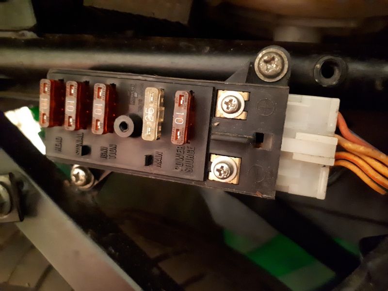
                                Thanks for the pic Lachie it helps confirm I have the right block since my plug wouldnt fit what you posted. Also answers my question about the red spare plug. Here's a pic of the fuse block.

                                You can see the red wire at the top. And my mistake in my earlier post when I said grey wire at the block. I ment the orange and blue. It has power at the block. when I follow the O/B from the block it leads to the plug for the right switch pod. On the battery side it enters as O/b but on the switch side the o/b just loops back to the plug and continues as grey on the other side and leads to the gauge lights.

                                So bare with me as I think this out. Key off only red should have power. Anything else I find with power I need to follow to the source.

                                I'm going to print off the wiring diagram as well as all your advice and tips so I can reference them easier next time I'm out there.

                                I've said it before but I really appreciate all the help you've all given me, particularly with this wiring. Taking the time to post pics and links and trying to explain things in simple terms for me really helps. I'll get it eventually! lol I may have to reread it all several times but I don't give up easy.

                                Comment

                                Working...
                                X