
 Tweet
Tweet
I'm sure everyones seen the original thread by now (http://katriders.com/vb/showthread.php?t=82182) but I wanted to make a much shorter version of the swap that had all of the tech and pics but without the discussion of various theories and ideas. This thread is clearly not the only way to do it, and probably isn't even the best way. But, my bike does run with this setup and once tuned correctly should offer many benefits over carbs. I'm not going to go into detail as to what the benefits are, as most of it was discussed in the aforementioned thread. Perhaps this could be stickied if it's in depth enough.
Lets start with the parts list. You'll need:
01-03 GSXR 600/750 throttle bodies. I recommend the 600s as theyre smaller and easier to fit onto a Katana engine. Make sure the ones you get come with the injectors and any accessories you might want. The 01-02 GSXR 1000 throttle bodies may also fit, but note that they changed to a new style in 2003.
Fuel pump. Must deliver at least 45psi. Aim for 45-60psi operating range. I went with an inline fuel pump, but if you're crafty you might be able to get an in-tank setup going, which makes for a cleaner look.
Fuel pressure regulator. Any regulator off any EFI vehicle should work as long as its set at 43-45psi. Note that many GM vehicles in the 80s and 90s use a TBI setup that runs at 20psi. You CANNOT use much of anything from these fueling systems.
***SEE NOTES***Megasquirt system. The exact variant isnt critical for a basic running engine, but the different versions allow for different features. There are two CPUs available (MS1 and MS2) and two boards (PCB 2.2 and 3.0). The CPU holds little relevance on an engine as simple as this. MS2 has native spark control, but MS1 can be flashed with custom firmware to do the same thing. The PCB is much more critical on this application. The Katana uses a VR sensor for the signal generator, and the 2.2 board does NOT have the capability to handle this signal without adding external parts. The 3.0 makes the install nice and clean. I have an MS1 2.2, but I recommend the MS1 3.0. Theres also the Microsquirt which is smaller and similar to a MS2 3.0. I'm not familiar with this route so I can't answer many questions about it. EDIT: I now recommend the MS1 2.2 combo as the VR decoder is no longer needed
Automotive fuel filter. Fuel injectors are clogged very easily and will not tolerate any dirt. These are cheap at any auto parts store.
Intake Air Temperature (IAT) sensor. This tells the MS unit the temp of the air for calculating air density. The recommended part is Duralast SU109 from Autozone. Cheap and effective. You may also use the same sensor for your oil temp sensor, mounted somewhere on the engine block.
Fuel hose. 5/16" for the most part. If its a pressurized line you MUST use EFI rated hose. Its more expensive but won't rupture. For return and feed hoses you can use standard fuel hose.
Oxygen sensor. I HIGHLY HIGHLY recommend a wideband sensor. A wideband tells you the exact AFR you're running at any given time. A narrowband only tells you rich or lean and is not very helpful and CANNOT be used to tune the high end or you'll end up melting pistons. I recommend the Innovate LC-1. You don't need the gauge, the MS handles it.
Optional parts:
Katana 750 intake boots. These are a few MM larger than the 600 boots. Either work, but the 600 boots need to be bored out with a dremel. Its easy to do, I wouldn't bother with the 750 parts.
Metal hose barbs. If you don't use the stock petcock (I didn't) youll need to make a hose adapter. You'll probably need to make one anyway for a return, but you might be able to get around that.
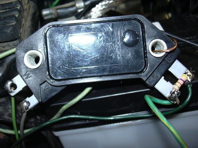
***SEE NOTES***GM 4 pin HEI module. Did you buy a PCB 3.0? Then ignore this part. This is needed by the 2.2 board to decode the VR signal from the bike and output a clean signal to the MS. Duralast part number DR100 from Autozone. This is no longer needed.
Aftermarket fuel rail. If you really really dont want to make this, then you can buy one drilled and cut to your liking. The only place I know of to get one from is ross machine racing. They have a website. I'd also check summitracing.com.
Special tools:
Welder. Makes things easier, but I'm sure theres ways around using one if you don't have one.
Grinder. To lengthen the fuel rail youll need to cut it in half and grind it smooth. A bench grinder is the best tool for this job, but I did it with a steady hand and a handheld angle grinder.
Laptop. It doesnt have to be a good one, in fact only the old ones have serial ports on them (to talk with the MS). You can get a USB-serial adapter if you need. The laptop doesn't need to be anything special as long as it can run windows.
Carb syncer. I use a Morgan Carbtune and it took 5 minutes to get it perfect. These may not be carbs, but they need to be synced all the same.
Basic electrical tools. You're going to need to solder here, so soldering equipment is a must. A digital multimeter is a nice tool to have as well.
That should be it for the shopping list. Lets begin!

You can see the comparison between the TBs and the carbs here. I've jumped the gun and already removed the secondary butterflies before this pic was taken. You MUST remove the secondaries if you want any power or drivability. This assembly commonly fails on GSXRs, so if you're careful in removing them you can probably resell them to the GSXR crowd. Heres a closeup of the secondary shaft:

Once you start removing them it's pretty easy. The only things on this entire assembly you need are the bodies themselves, the injectors, the primary throttle plates, and the throttle linkage so don't be shy in tearing them down.
Here is one of the main reasons this has not been done before:

With cylinder 1 lined up perfectly between the carbs and TBs, notice the port spacing difference. Cyl 2 is off, 3 is way off, and 4 is a little off. Fortunately this generation GSXR has modular throttle bodies: they all come apart with ease. Its just a matter of altering the spacing to make them fit.
For reference, here is a pic of the overall height difference:

You'll have to use your imagination a little bit as my carbs are not completely together.
So now how do we mate these up to the engine? The stock intake boots are made of soft rubber, and even the stock 600 boots will fit over the TBs without deforming:


This was a very tight fit, and I highly doubt you'll be able to fit the TBs into the boots while the boots are bolted to the motor. Pressing it in took much force. What I decided to do to make it workable (due to the Katana frame, all 4 throttles MUST be installed at once or you won't be able to fit the bolts in) was pack some paper towels down the intake ports and slowly grind down the inside of the boots with a dremel. It makes a mess, and you don't want this junk in your motor. Theres a small rib in the rubber, if you grind that flush with the rest of the boot it should fit alright. I did flush and then another millimeter or two over that. Dont overdo it or youll have vacuum leaks. After grinding but BEFORE removing the paper towels, blow the ports out. An air compressor works well here, but whatever you can do should be fine. The end result of this step is pleasing, as you now have something to show for your troubles:


Well, that wasn't so hard. But what to do about the gap from spacing them out?

First and foremost, you'll need some washers to go between the center two throttles. Without them theyll flex under twisting the throttle and youll never ever get them to hold sync. At this point I'd like to mention that my throttle bodies are actually installed upside down! With them oriented correctly, the fuel rail is on the bottom of the throttles. This would be a good thing normally as air wouldn't get stuck down there. But on a Katana, the fuel rail hits the alternator and wont fit. Having them upside down doesnt hurt anything but does bring up a few issues that we'll deal with later. With the fuel rail on top, it clears the tank by just enough:

Enough gap for safety, but close enough to be a lucky fit. This is on a Pre, hopefully the 98+ tank doesnt extend any lower. Your petcock is going to hit the rail by just a little bit. You can probably dent the bottom of the tank in a cm or two to clearance it. My petcock was shot so I made my own out of some steel, a hose barb, and some JBweld:

But back to the other problem with the throttle spacing: the throttle linkage. As you saw in the picture, its not even close to being long enough. The length of the arm has to be extended by about 8mm. I was able to weld a piece of metal to the end of the arm to bridge the gap. Try to make it flat if you can, but if not perfect you'll take care of it while syncing anyway.

That weld was just a tack for fitment. I don't have a pic of the finished weld, but the positioning didn't change from that picture. Now that you've lengthened the linkage its time for the 2nd half of the job: the fuel rail. You've got options again. Buy fuel rail stock from an aftermarket supplier, build your own rail from a piece of square metal tube, or modify the GSXR part. I was weary of doing this at first but was soon reminded that the rail was worthless to me anyway since it didnt fit. I started with this:

Cut it in half:

No chance in hell it'll seal with those casting ridges, so they've gotta go:

Both sides ground smooth:

And then test fitted to the motor:


And bridged with heater hose of a forgotten diameter:

Now hows that for a stupid idea that ended up working great? Doesn't leak a drop! Dont worry about the pressure rating of that hose. The gap is too short to allow for any swelling. Next up is the throttle cable. Remember how I said the throttle bodies are upside down? Heres one of those issues I mentioned:

This pic is looking at cylinder 4 from the seat area. Looking closely youll see the throttle cable mounts are now on bottom. I'm not sure how to advise you on this one if you don't have access to a welder, but I'll show you my solution to maybe spark an idea:


I welded the adjuster nut to the throttle stop on the cable pulley assembly. This allowed the cable to come in from the top as well as have 100% range of motion. The GSXR must have a very long cable, as you would need about 4-5 inches of exposed cable to use this damn thing. If you cant weld, maybe try buying a GSXR cable. You might be able to find a way to make this work easier.
If you've made it this far, congratulations! All of the major puzzle pieces are now in place. All thats left is the fuel system and wiring harness. Lets go over the fuel system first.
When I started this I had the following diagram in my head knowing that it had only a 40% chance of success:
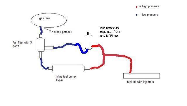

I built this, and as expected, after 10 minutes or so the fuel-cooled fuel pump had heated itself and the metal fuel filter to the point of burning your hand. The gas was evaporating in the lines and bleeding the air out of there took forever each time it happened. This diagram was always known to be the "correct" way that had a 95% chance of success:

So then why didnt I do that in the first place? Lazyness. I didnt want to drill a hole in my gas tank. What I ended up doing was drilling the return in the metal plate for the fuel sender. Worked perfectly and didnt change the tank from stock. Unfortunately I don't have a pic of this one. It looked the same as the first, but with the hole drilled in the sender rather than a new plate. The reason this one works is that the heated fuel is sent back to the tank to cool off for several minutes before recirculating. With the other setup it repumped the same gas over and over again.
The other concern for having the throttles upside down is air bubbles. Its a returnless system, so bubbles never get pushed out. The fuel rail is the high point of the system so it collects a lot of air. I changed it up from my earlier pic to have the T level with the valve cover and the regulator on top of the valve cover. The high point is now the FPR instead of the rail, so air is simply pushed back into the tank and dissipated. Pics to come soon, I was working fast and didnt take any work-in-progress shots.
The last thing I'll cover in this chapter is the misc welding. On a pre98, there is no real tray to mount the MS unit. But I found it fits perfectly under the passenger seat. I welded some steel up to form a flat tray and bolted the MS down. I recommend making a watertight box for the MS (not microsquirt though, its watertight) if you dont live in the hell that is Arizona. It never rains here, so I didnt bother.


Lastly you'll need to weld in a bung for the O2 sensor. All widebands are heated sensors, so distance from the header isnt critical, but closer is better. I placed mine directly behind the oil pan, tilting slightly upward to keep it out of harms way.


The bung used comes with the Innovate LC-1 I mentioned. Its a great little package for less than $200. It's 4am and I'm tired of typing so I'll cover the wiring in the next day or so. Then following that, chapter 3 will be about tuning. That has to wait until I'm actually finished tuning mine though. Expect posted fuel maps within a week and a half at the very latest.
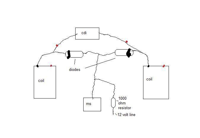
EDIT: After much experimenting, I have found that while the HEI module works, I do NOT recommend it. Theres a better way, which I'll cover in the wiring section. You can omit the 3.0 board and the HEI module as a result. Note that the 3.0 board still works fine, but its no longer required.
Lets start with the parts list. You'll need:
01-03 GSXR 600/750 throttle bodies. I recommend the 600s as theyre smaller and easier to fit onto a Katana engine. Make sure the ones you get come with the injectors and any accessories you might want. The 01-02 GSXR 1000 throttle bodies may also fit, but note that they changed to a new style in 2003.
Fuel pump. Must deliver at least 45psi. Aim for 45-60psi operating range. I went with an inline fuel pump, but if you're crafty you might be able to get an in-tank setup going, which makes for a cleaner look.
Fuel pressure regulator. Any regulator off any EFI vehicle should work as long as its set at 43-45psi. Note that many GM vehicles in the 80s and 90s use a TBI setup that runs at 20psi. You CANNOT use much of anything from these fueling systems.
***SEE NOTES***Megasquirt system. The exact variant isnt critical for a basic running engine, but the different versions allow for different features. There are two CPUs available (MS1 and MS2) and two boards (PCB 2.2 and 3.0). The CPU holds little relevance on an engine as simple as this. MS2 has native spark control, but MS1 can be flashed with custom firmware to do the same thing. The PCB is much more critical on this application. The Katana uses a VR sensor for the signal generator, and the 2.2 board does NOT have the capability to handle this signal without adding external parts. The 3.0 makes the install nice and clean. I have an MS1 2.2, but I recommend the MS1 3.0. Theres also the Microsquirt which is smaller and similar to a MS2 3.0. I'm not familiar with this route so I can't answer many questions about it. EDIT: I now recommend the MS1 2.2 combo as the VR decoder is no longer needed
Automotive fuel filter. Fuel injectors are clogged very easily and will not tolerate any dirt. These are cheap at any auto parts store.
Intake Air Temperature (IAT) sensor. This tells the MS unit the temp of the air for calculating air density. The recommended part is Duralast SU109 from Autozone. Cheap and effective. You may also use the same sensor for your oil temp sensor, mounted somewhere on the engine block.
Fuel hose. 5/16" for the most part. If its a pressurized line you MUST use EFI rated hose. Its more expensive but won't rupture. For return and feed hoses you can use standard fuel hose.
Oxygen sensor. I HIGHLY HIGHLY recommend a wideband sensor. A wideband tells you the exact AFR you're running at any given time. A narrowband only tells you rich or lean and is not very helpful and CANNOT be used to tune the high end or you'll end up melting pistons. I recommend the Innovate LC-1. You don't need the gauge, the MS handles it.
Optional parts:
Katana 750 intake boots. These are a few MM larger than the 600 boots. Either work, but the 600 boots need to be bored out with a dremel. Its easy to do, I wouldn't bother with the 750 parts.
Metal hose barbs. If you don't use the stock petcock (I didn't) youll need to make a hose adapter. You'll probably need to make one anyway for a return, but you might be able to get around that.
***SEE NOTES***GM 4 pin HEI module. Did you buy a PCB 3.0? Then ignore this part. This is needed by the 2.2 board to decode the VR signal from the bike and output a clean signal to the MS. Duralast part number DR100 from Autozone. This is no longer needed.
Aftermarket fuel rail. If you really really dont want to make this, then you can buy one drilled and cut to your liking. The only place I know of to get one from is ross machine racing. They have a website. I'd also check summitracing.com.
Special tools:
Welder. Makes things easier, but I'm sure theres ways around using one if you don't have one.
Grinder. To lengthen the fuel rail youll need to cut it in half and grind it smooth. A bench grinder is the best tool for this job, but I did it with a steady hand and a handheld angle grinder.
Laptop. It doesnt have to be a good one, in fact only the old ones have serial ports on them (to talk with the MS). You can get a USB-serial adapter if you need. The laptop doesn't need to be anything special as long as it can run windows.
Carb syncer. I use a Morgan Carbtune and it took 5 minutes to get it perfect. These may not be carbs, but they need to be synced all the same.
Basic electrical tools. You're going to need to solder here, so soldering equipment is a must. A digital multimeter is a nice tool to have as well.
That should be it for the shopping list. Lets begin!
You can see the comparison between the TBs and the carbs here. I've jumped the gun and already removed the secondary butterflies before this pic was taken. You MUST remove the secondaries if you want any power or drivability. This assembly commonly fails on GSXRs, so if you're careful in removing them you can probably resell them to the GSXR crowd. Heres a closeup of the secondary shaft:
Once you start removing them it's pretty easy. The only things on this entire assembly you need are the bodies themselves, the injectors, the primary throttle plates, and the throttle linkage so don't be shy in tearing them down.
Here is one of the main reasons this has not been done before:
With cylinder 1 lined up perfectly between the carbs and TBs, notice the port spacing difference. Cyl 2 is off, 3 is way off, and 4 is a little off. Fortunately this generation GSXR has modular throttle bodies: they all come apart with ease. Its just a matter of altering the spacing to make them fit.
For reference, here is a pic of the overall height difference:
You'll have to use your imagination a little bit as my carbs are not completely together.
So now how do we mate these up to the engine? The stock intake boots are made of soft rubber, and even the stock 600 boots will fit over the TBs without deforming:
This was a very tight fit, and I highly doubt you'll be able to fit the TBs into the boots while the boots are bolted to the motor. Pressing it in took much force. What I decided to do to make it workable (due to the Katana frame, all 4 throttles MUST be installed at once or you won't be able to fit the bolts in) was pack some paper towels down the intake ports and slowly grind down the inside of the boots with a dremel. It makes a mess, and you don't want this junk in your motor. Theres a small rib in the rubber, if you grind that flush with the rest of the boot it should fit alright. I did flush and then another millimeter or two over that. Dont overdo it or youll have vacuum leaks. After grinding but BEFORE removing the paper towels, blow the ports out. An air compressor works well here, but whatever you can do should be fine. The end result of this step is pleasing, as you now have something to show for your troubles:
Well, that wasn't so hard. But what to do about the gap from spacing them out?
First and foremost, you'll need some washers to go between the center two throttles. Without them theyll flex under twisting the throttle and youll never ever get them to hold sync. At this point I'd like to mention that my throttle bodies are actually installed upside down! With them oriented correctly, the fuel rail is on the bottom of the throttles. This would be a good thing normally as air wouldn't get stuck down there. But on a Katana, the fuel rail hits the alternator and wont fit. Having them upside down doesnt hurt anything but does bring up a few issues that we'll deal with later. With the fuel rail on top, it clears the tank by just enough:
Enough gap for safety, but close enough to be a lucky fit. This is on a Pre, hopefully the 98+ tank doesnt extend any lower. Your petcock is going to hit the rail by just a little bit. You can probably dent the bottom of the tank in a cm or two to clearance it. My petcock was shot so I made my own out of some steel, a hose barb, and some JBweld:
But back to the other problem with the throttle spacing: the throttle linkage. As you saw in the picture, its not even close to being long enough. The length of the arm has to be extended by about 8mm. I was able to weld a piece of metal to the end of the arm to bridge the gap. Try to make it flat if you can, but if not perfect you'll take care of it while syncing anyway.
That weld was just a tack for fitment. I don't have a pic of the finished weld, but the positioning didn't change from that picture. Now that you've lengthened the linkage its time for the 2nd half of the job: the fuel rail. You've got options again. Buy fuel rail stock from an aftermarket supplier, build your own rail from a piece of square metal tube, or modify the GSXR part. I was weary of doing this at first but was soon reminded that the rail was worthless to me anyway since it didnt fit. I started with this:
Cut it in half:
No chance in hell it'll seal with those casting ridges, so they've gotta go:
Both sides ground smooth:
And then test fitted to the motor:
And bridged with heater hose of a forgotten diameter:
Now hows that for a stupid idea that ended up working great? Doesn't leak a drop! Dont worry about the pressure rating of that hose. The gap is too short to allow for any swelling. Next up is the throttle cable. Remember how I said the throttle bodies are upside down? Heres one of those issues I mentioned:
This pic is looking at cylinder 4 from the seat area. Looking closely youll see the throttle cable mounts are now on bottom. I'm not sure how to advise you on this one if you don't have access to a welder, but I'll show you my solution to maybe spark an idea:
I welded the adjuster nut to the throttle stop on the cable pulley assembly. This allowed the cable to come in from the top as well as have 100% range of motion. The GSXR must have a very long cable, as you would need about 4-5 inches of exposed cable to use this damn thing. If you cant weld, maybe try buying a GSXR cable. You might be able to find a way to make this work easier.
If you've made it this far, congratulations! All of the major puzzle pieces are now in place. All thats left is the fuel system and wiring harness. Lets go over the fuel system first.
When I started this I had the following diagram in my head knowing that it had only a 40% chance of success:
I built this, and as expected, after 10 minutes or so the fuel-cooled fuel pump had heated itself and the metal fuel filter to the point of burning your hand. The gas was evaporating in the lines and bleeding the air out of there took forever each time it happened. This diagram was always known to be the "correct" way that had a 95% chance of success:
So then why didnt I do that in the first place? Lazyness. I didnt want to drill a hole in my gas tank. What I ended up doing was drilling the return in the metal plate for the fuel sender. Worked perfectly and didnt change the tank from stock. Unfortunately I don't have a pic of this one. It looked the same as the first, but with the hole drilled in the sender rather than a new plate. The reason this one works is that the heated fuel is sent back to the tank to cool off for several minutes before recirculating. With the other setup it repumped the same gas over and over again.
The other concern for having the throttles upside down is air bubbles. Its a returnless system, so bubbles never get pushed out. The fuel rail is the high point of the system so it collects a lot of air. I changed it up from my earlier pic to have the T level with the valve cover and the regulator on top of the valve cover. The high point is now the FPR instead of the rail, so air is simply pushed back into the tank and dissipated. Pics to come soon, I was working fast and didnt take any work-in-progress shots.
The last thing I'll cover in this chapter is the misc welding. On a pre98, there is no real tray to mount the MS unit. But I found it fits perfectly under the passenger seat. I welded some steel up to form a flat tray and bolted the MS down. I recommend making a watertight box for the MS (not microsquirt though, its watertight) if you dont live in the hell that is Arizona. It never rains here, so I didnt bother.
Lastly you'll need to weld in a bung for the O2 sensor. All widebands are heated sensors, so distance from the header isnt critical, but closer is better. I placed mine directly behind the oil pan, tilting slightly upward to keep it out of harms way.
The bung used comes with the Innovate LC-1 I mentioned. Its a great little package for less than $200. It's 4am and I'm tired of typing so I'll cover the wiring in the next day or so. Then following that, chapter 3 will be about tuning. That has to wait until I'm actually finished tuning mine though. Expect posted fuel maps within a week and a half at the very latest.
EDIT: After much experimenting, I have found that while the HEI module works, I do NOT recommend it. Theres a better way, which I'll cover in the wiring section. You can omit the 3.0 board and the HEI module as a result. Note that the 3.0 board still works fine, but its no longer required.


 awesome dude, just awesome!


Comment